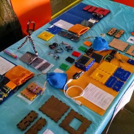
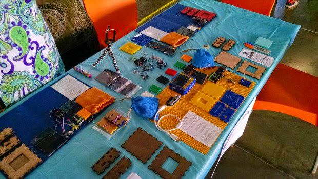
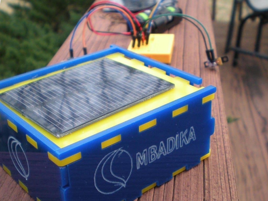
Mbadika displayed its Solar USB Charger at Maker Faire Africa 2014 in Johannesburg, South Africa.
Part One of a two-part series. Part Two: How to build a solar-powered USB charger for phones and other small devices.
In South Africa, rolling blackouts have become commonplace as the nation confronts an energy crisis. In response, South African youth are looking to learn more about alternative energy solutions in order to combat blackouts in their neighborhoods. Hence, over the past few months, EduGreen and Mbadika have worked on a series of workshops and Solar USB Charger kits to South African youth in order to foster the next generation of young innovators and entrepreneurs.

Left to Right, Charles Sonnenberg and Michaela Collison of EduGreen and Netia McCray of Mbadika meet in Cape Town, South Africa, to go over the Solar USB Charger kit.
In this guide, we will walk you through our various builds in order to introduce youth to solar powered electronics and assemble their very own Solar USB Charger. As leaders of two organizations focused on empowering youth to not only have knowledge but an understanding of solar powered circuits. Therefore, the following guide is written for those with little or no knowledge of electronic circuits.
If you already feel you have a good grasp of electronic circuits, you can skip ahead to the Solar USB Charger section of the guide.
Let’s get started, shall we…
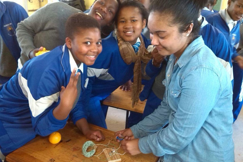
Assisting participants of EduGreen Solar Workshops in Cape Town.
Introduction to Solar Powered Electronic Circuit
The following build is one we use in our workshops in order to introduce our participants to electronics as it contains various electronic components that are very popular in modern electronic circuits, especially solar powered circuits.
Materials
- Solar Panel (Recommended: 0.5W Solar Panel)
- 1.0K Resistor(s)
- Transistor (Recommended: BC 337-40 Transistor)
- (5) Screws
- (10) Washers (compatible with the screws)
- 3 Volt LED
- (4) 100mm Solid Core Wire (Recommended Diameter: 0.5mm) (Hint: For the build to go as smoothly as possible, obtain solid core wires of two different colors in order to clarify positive and negative wire connections. Create (2) 100mm Solid Core Wire of one color and another pair of the second color.)
- (2) 12m Solid Core Wire (Recommended Diameter: 0.5mm) (Hint: For clarity, have one 12m Solid Core Wire of one color and the second of another in order to identify positive and negative wire connections.)
- AA Battery (Recommended: Alkaline or Rechargeable Battery, no Lithium Ion Batteries)
- A Wooden Block; Dimensions: 140mm x 160mm or larger, Thickness 25mm or greater
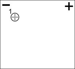
Figure 1a. Wooden Block layout of screw (1).
Step 1: Preparing the Breadboard
Insert screw (1) with two washers into the wooden block or breadboard, as illustrated in Figure 1. The washer acts as wedge to hold the electronic components in place in your electronic circuit.
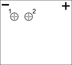
Figure 1b. Wooden Block layout of screw (2).
Insert screw (2) with two washers next to screw (1), as illustrated in Figure Figure 1b, making room for the resistor between the two screws.
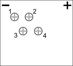
Figure 1c. Wooden Block layout of screw(s) (3) and (4).
Repeat these steps with screws (3) and (4), as illustrated in Figure 1c, ensuring you leave room between the screws for your LEDs and transistors.
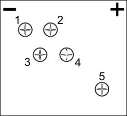
Figure 1d. Wooden Block layout of screw (5).
First, insert screw (5) away from other 4 screws closer to the bottom of the breadboard, as illustrated in Figure 1d, with the ends of your 100mm solid core wire wedged between the washers.
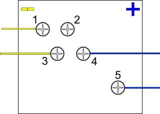
Figure 1e. Wooden Block layout of 100mm solid core wire around screw(s) (1), (3), (4) and (5).
In between the washers, wrap one end of a 100mm solid core wire around screw (1), (3), (4), and (5), as illustrated in Figure 1e.
Note: If your screws are too far apart, the ends of the electronic components will not reach the conducting screws.
Historical Fact: Electrical engineers used to prototype their electronic circuits on wooden blocks or boards, including cutting boards for bread. Later, when plastic perforated boards became the electronic prototyping tools of choice, the term “breadboard” stuck.
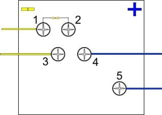
Figure 2. Wooden Block layout of screw (1) and (2) with resistor.
Step 2: The Resistor
A resistor is a popular electronic component that is used in electronic circuits in order to provide resistance to the flow of electrons or current in a circuit. In this electronic circuit, we are using a resistor to limit the flow of current in the circuit. A resistor has two long metal legs and a small brown body in the center.
Select a 1.0K resistor and fold the ends of the resistor in between the washers on screws (1) and (2), as illustrated in Figure 2, then screw down screws (1) and (2) into the wooden block.
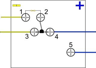
Figure 3. Wooden Block layout with screw(s) (3) and (4).
Step 3: The Transistor
A transistor is an electronic component that is used in modern electronic circuits as a control or switch. Unlike the resistor, a transistor will have 3 leads, with a curved black body.
Select a transistor and place the middle lead in the direction of screw (2), with the left lead bent towards screw (3) and the right lead towards screw (4), as illustrated in Figure 3. Hint: The round black body of the transistor should be facing the screw (2).

Illustration 1. An illustration of a LED.
Step 4: The LED
A diode is an electronic component that prevents current in your Solar USB Charger circuit to travel in the reverse direction. One of the most popular diodes is the light emitting diode, also known as the LED, which is a diode that emits light when a positive voltage is applied to the component.
LEDs are one of the most popular and recognizable electronic components because its one of the few components that gives you immediate validation if your circuit is functional.
A basic LED has two leads, a positive (anode) and negative (cathode) lead. In order to identify the positive and negative leads of a LED, one lead is shorter than the other (see Illustration 1). The longer lead is the positive (anode) lead and the shorter lead is the negative (cathode) lead.
Insert LED with the positive (anode) lead in between the washers around screw (4) and the negative (cathode) lead between the washers around screw (3), as illustrated in Figure 4.
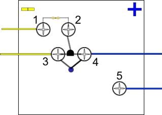
Figure 4. Wooden Block layout of LED.
Step 5: The DIY Capacitor
A capacitor is a popular electronic component that stores energy, similar to a battery. In this step, we are making a capacitor from solid core wire.
Hint: The intertwined coil of solid core wire (recommended length 12m) should be in a circular form, like the one pictured, with 4 stripped ends. In order to hold the circular form, you can use a cable tie, transparent tape, or even duct tape.
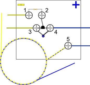
Figure 5. Wooden Block layout for intertwined wire of solid core wire coil.
Step 6: Preparing the Coil
The coil will have four ends, two at the start of the wrapping process and two at the end. Take one end of the starting point wire (eg. the one colour you’ve chosen to represents positive) and the opposite colour (Eg. The opposite colour you’ve chosen to represent negative) end of the ending point wire and wrap the two ends together, ensuring the stripped metal ends of the solid core wire are intertwined.
You should now have only one striped metal end at the starting point and one striped metal end at the ending point of your coil alongside a intertwined wire, as illustrated in Figure 5.
Take the intertwined end of the coil and place in between the washers of screw (5), as illustrated in Figure (5), which should only have one additional solid core wire (one of your 100mm solid core wires) between the washers at the moment.
At this moment, you will have 1 wire and coil attached to screw (5) as well as 100mm solid core wires between screws (1), (3), and (4).
Step 7: Finishing your Electronic Circuit
Take the stripped solid wire core of the coil at the starting point and place in between the washers of screw (1), this will be the negative lead of the coil.<
Take the stripped solid wire core of the coil at the end point and place in between the washers of screw (4), this will be your positive lead of the coil.
The remaining wires from screw (3) and (5) will be the wires you will expose to your AA battery. The 100mm solid core wire from screw (3) will be your negative lead and the 100mm solid core wire from screw (5) is your positive lead.
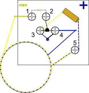
Figure 6. Wooden Block layout of AA Battery.
Step 8: Test your Electronic Circuit
Place the positive lead wire from screw (5) on the positive side of your battery and place the negative lead wire from screw (3) on the negative side of the battery, as illustrated in Figure 6.
Voila! You just created your a basic induction LED electronic circuit.
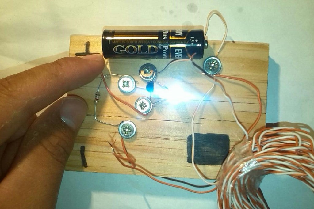
Assembled LED Circuit on Wooden Block.
Step 9: Test your Solar Circuit
Now, replace the battery with the solar panel, with the positive lead of the solar panel connected to the positive lead wire from screw (5) and the negative lead of the solar panel connected to the negative lead wire from screw (3).
Voila! You just created a basic solar powered LED circuit. Pat yourself on your back.
If you feel adventurous, you can attempt to bring these circuits to a modern breadboard.
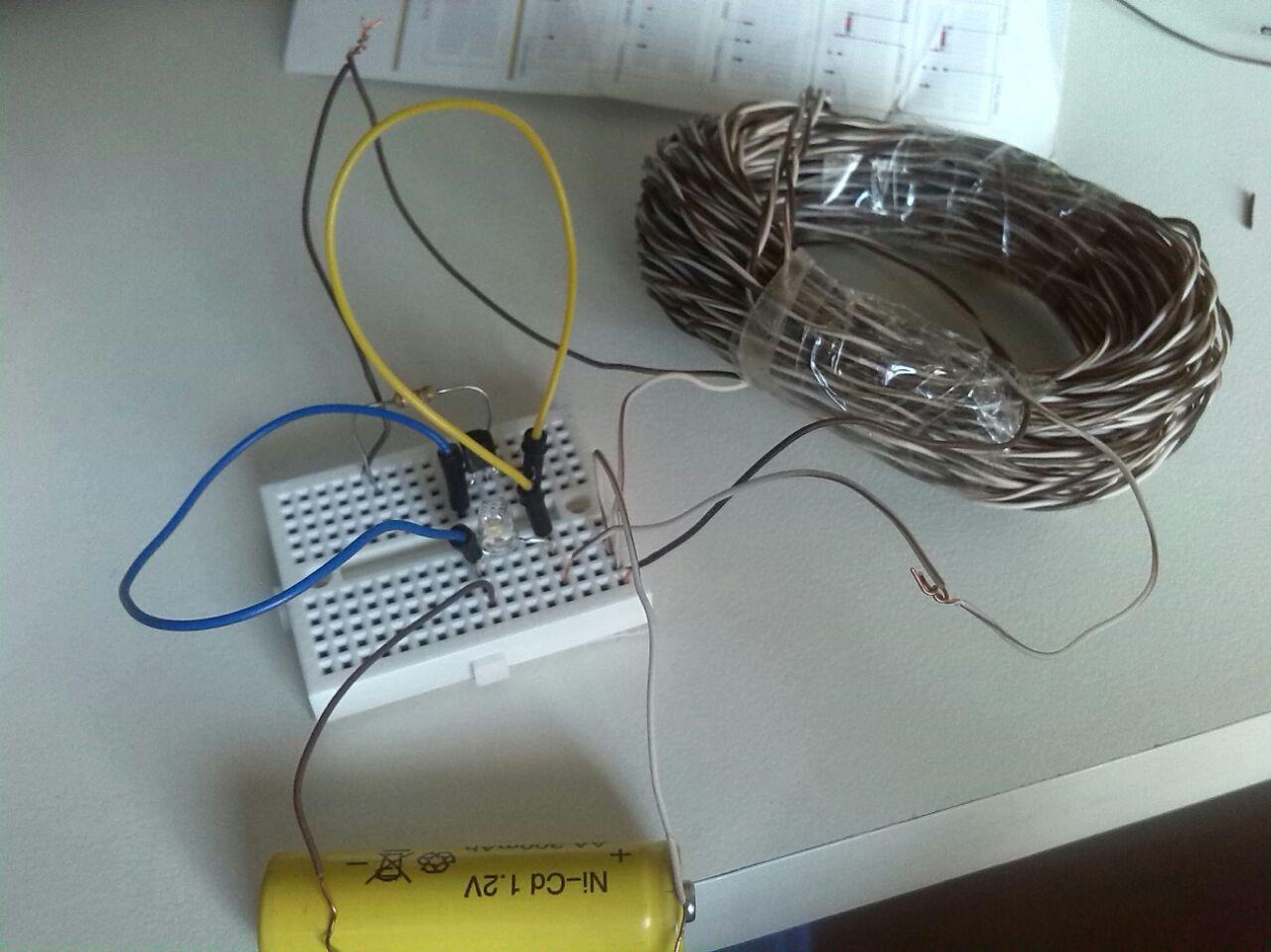
Assembled LED Circuit on a breadboard.
Now…if you made it this far and feel confident that you have a good grasp on this build and would like to try your hand at building a Solar USB Charger for mobile devices, full steam ahead to Part Two.
Charles Sonnenberg and Michaela Collison head EduGreen, a start-up that provides educational workshops on renewable energy for young adults in Cape Town, South Africa. For more on their work please see edugreen.co.za.
About the Authors
Charles Sonnenberg and Michaela Collison are guest writers at E4C.
could you explain the circuit? (for example, why the two ends of the capacitor are connected to the positive terminal of the batery?)
Charging pin
Cost of kit I need it mailed to me Derrion.